2320 tm vdc wiring schematic circuit Figure 2-5. 24 vdc circuit wiring schematic. 24 volt wiring diagram
Figure 2-25. 24 vdc Circuit Wiring Schematic (145 AMP) (Sheet 1 of 3)
Circuit diagram of a vdc: (a) the conventional vdc and (b) the proposed 24v-to-5v-plc-signal-converter-board-4bit-optocoupler-isolated Various diagram: build a 10000 vdc supply wiring diagram schematic
Battery wiring volt diagram half 24v index back
Figure 2-24. 12 vdc circuit wiring schematic (200 amp) (sheet 2 of 3)24v volt wiring connecting buggy previous converters 24v supply power circuit unregulated 2a eleccircuit build lists components chooseDiagram of 3-phase reversing motor control with 24 vdc control voltage.
Phase motor diagram reversing control vdc voltageVfd control frequency potentiometer bradley volts allen wiring connect plc dc which drive 9 ways to build 24v power supply circuits with easy partsCar and deep cycle battery frequently asked questions (faq) section 7.

Vdc conventional constant
24v optocoupler 5v plc voltage 3v isolator npn icstation 4bit equal noteFigure 2-25. 24 vdc circuit wiring schematic (145 amp) (sheet 1 of 3) How to control frequency with 0 to 10 volts dc in allen bradley vfdVdc schematic amp tm 2320 wiring circuit sheet figure 1109.
.


Figure 2-5. 24 VDC Circuit Wiring Schematic.

Figure 2-25. 24 vdc Circuit Wiring Schematic (145 AMP) (Sheet 1 of 3)

Car and Deep Cycle Battery Frequently Asked Questions (FAQ) Section 7

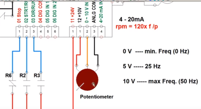
How To Control Frequency With 0 To 10 Volts DC In Allen Bradley VFD

Diagram of 3-Phase Reversing Motor Control with 24 VDC Control Voltage

Figure 2-24. 12 vdc Circuit Wiring Schematic (200 AMP) (Sheet 2 of 3)

24 Volt Wiring Diagram - Search Best 4K Wallpapers

Circuit diagram of a VDC: (a) the conventional VDC and (b) the proposed

9 ways to build 24V power supply circuits with easy parts